WEEK 4:
ELECTRONIC PRODUCTION.
I started the week learning how to use the mods program, to export the PNG image of the circuit that needs to be done in practice.
The first inconvenience is that in our institution we still do not have the machines installed, for this I have made the documentation of the steps that I have to carry out to assemble the circuit of the task.
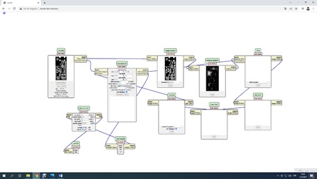
Exploring the mods.
group assignment:
Characterize the design rules for your in-house PCB production process
Extra credit: send a PCB out to a board house
Individual assignment:
make an in-circuit programmer that includes a microcontroller:
Extra credit: customize the design
Mill and stuff the PCB
Test it to verify that it works
Extra credit: try other PCB processes
The project was to make a circuit board, definitely one where I learned new electronics knowledge to make the circuits.
First I started the task by downloading the images of the circuit to be made:
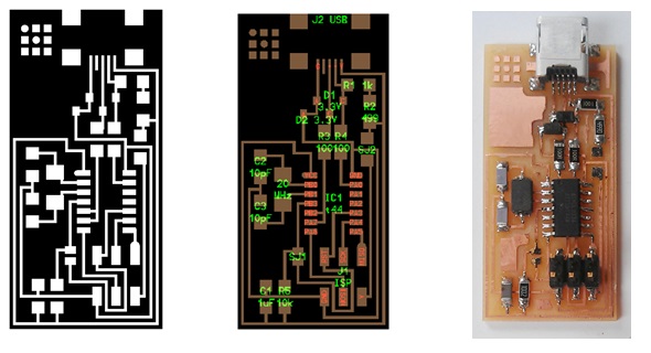
List of electronic circuit components:
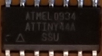
- IC1 t44 is a microchip. ATMEL 0934 ATTINY44A
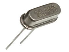
– XTAL1 20 MHz is a resonator. A crystal oscillator is an electronic oscillator that uses the mechanical resonance of a vibrating crystal of piezoelectric material to create an electrical signal with a precise frequency.
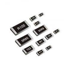
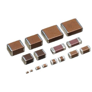
– R1 1k, R2 499 Ω, R3 and R4 100 Ω R5 10K, are SMD resistors.
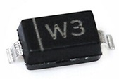
– 3.3V Zener diodes
– C1 1uF, C2 and C3 10pF. They are capacitors
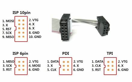
– J1 ISP is a microcontroller, listed in AVRISPSMD
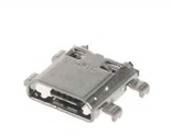
– J2 USB is a USB port
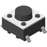
– SJ1 is a Switch
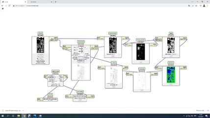
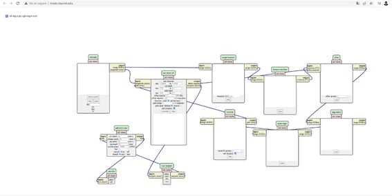
Using the Mods
1. We open the shortcut to mods.2. Right click on the white screen -> Programs -> open server program
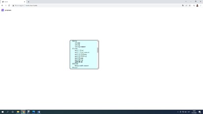
3. Scroll to the machines section and search for G – Code Mill 2D png which is a program to be used on any machine.
4. Select in the program the printed circuit png hello.ISP.44. traces
5. Calculate the generated toolpath for milling purposes